
Mechanical mounting
- Panel shoulder, mounting thread, washer and locknut
- Panel thickness and mounting-hole diameter
- Wrench access, installation direction and anti-rotation requirement
Through-panel hydraulic bulkhead fittings manufactured to customer drawings for routing tube and hose connections through equipment panels, brackets and machine frames.
A bulkhead fitting is a through-panel mounting structure, not a separate thread or sealing standard. Its shoulder, washer and locknut primarily provide mechanical retention; the fluid seal at each end must be confirmed for that connection. A tank wall or other fluid boundary needs a separate, drawing-defined panel seal. Straight, elbow, reducing, extended-length and mixed-interface bodies can be machined to approved drawings.
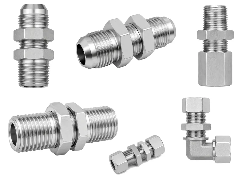
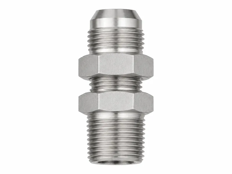
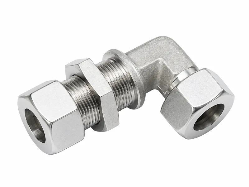
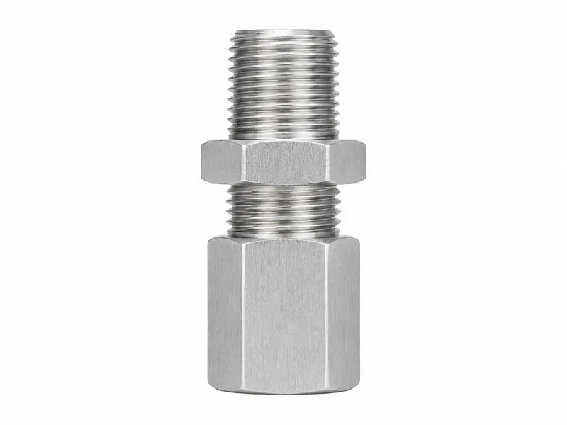
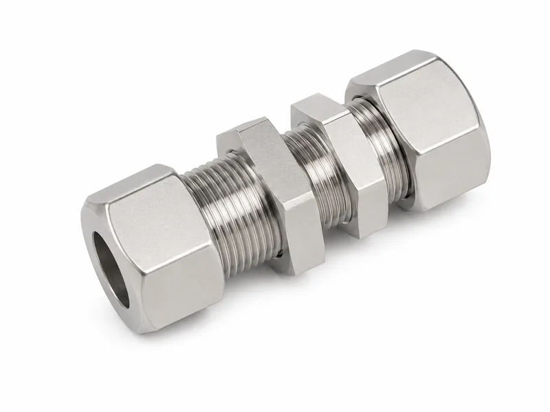
Wei Xing Machinery manufactures custom hydraulic bulkhead fittings and hydraulic panel connectors from approved 2D drawings, 3D models, verified samples and order requirements. We review the mounting interface and both end connections independently before production.
End-connection geometry can be manufactured to the customer-specified connection standard when identified on the approved drawing or order. Production availability depends on drawing review, material, tooling and quantity.
| Product Type | Panel-mount or through-panel hydraulic fitting; bulkhead describes the mounting structure, not an independent sealing standard. |
|---|---|
| Mounting Function | Provides a fixed routing point through a panel, bracket or frame. |
| End Connection Options | JIC 37°, ORFS, BSPP, BSPT, NPT, metric, hose or drawing-specific; each end is confirmed separately. |
| Panel Interface | Panel thickness, hole diameter, mounting length, shoulder, washer, locknut engagement, protrusion, access, direction and anti-rotation per drawing. |
| Panel-Seal Requirement | A fluid boundary requires a separate panel-seal design specified by the approved drawing. |
| Mounting Hardware | Drawing-defined washer and locknut quantity, position and dimensions; the locknut primarily provides mechanical retention. |
| Body Materials | Carbon steel, stainless steel, reviewed brass, or other drawing-approved material. |
| Surface Finish | Drawing- and material-compatible finish coordinated to order requirements. |
| Manufacturing Basis | Approved 2D drawing, 3D model, verified sample or order requirements. |
| Inspection Basis | Approved drawing and agreed sampling or full-inspection plan. |
| Pressure / Validation Basis | No uniform rating is defined here; tests are performed when specified by the approved drawing, order or agreed validation plan. |
| Applications | Machine frames, mounting panels, brackets, power units and drawing-defined sealed penetrations. |
A frame, bracket, guard, cabinet or mounting plate normally requires mechanical mounting review rather than sealing of the opening.
A tank, reservoir, fluid chamber wall or wet sealed enclosure needs a separately specified panel seal. Possible drawing-defined solutions include an O-ring and machined gland, bonded seal, compatible gasket, sealing washer, welded boss, or brazed/welded penetration. Confirm seal type and surface, groove or gasket dimensions, flatness, surface condition, corrosion compatibility and specified inspection.
Support tube and hose routing appropriately. Do not pull misaligned lines into place or place all side load, hose bending reaction, vibration or shock on the fitting. The equipment designer must specify anti-rotation features and mounting loads when needed; no general locknut torque is given here.
Drawing-specific sealed panel penetrations are a separate engineered category from ordinary locknut-retained fittings. Available configurations depend on drawing review, material, tooling, mounting requirements and production requirements; this list does not imply stock availability.
| Connection / Mounting Type | Panel Retention | Fluid Sealing | Selection Considerations |
|---|---|---|---|
| Bulkhead fitting | Passes through the panel and is retained by a shoulder, washer and locknut. | Confirmed separately at both ends. | Verify panel dimensions, access, loads and both connections. |
| Inline adapter | Normally none. | Defined by its two line connections. | Connects two lines without normally providing panel retention. |
| Hose fitting | Not inherently a panel mount. | Hose stem or crimp end plus specified connection. | Assembly capability depends on hose, ferrule, crimp and interface. |
| Drawing-specific sealed tank penetration | As engineered by the drawing. | The panel opening uses an engineered seal or welded structure. | Must not be treated as an ordinary bulkhead fitting. |
| End Connection | Primary Sealing Location | Assembly Function | Information to Confirm |
|---|---|---|---|
| JIC 37° | 37° metal flare surfaces | Straight thread supplies clamping force. | Standard, size, sex, mating flare and assembly requirement. |
| ORFS | O-ring against a flat face | Straight thread supplies assembly force. | Size, sex, O-ring, face and mating component. |
| BSPP | Depends on fitting and port design | Straight thread retains the connection. | Port form and face, washer, O-ring or cone design. |
| BSPT | Taper-thread engagement | Thread engagement supports sealing with applicable sealant. | Thread size, mating form, engagement and sealant. |
| NPT | Taper-thread engagement | Thread engagement supports sealing with compatible sealant. | Thread size, mating form, engagement and sealant compatibility. |
| Metric or drawing-specific | As defined by the drawing | Depends on the specified design. | Thread, sealing face, O-ring, cone or other geometry. |
A bulkhead adapter may use different connection and sealing principles at its two ends. Conversion combinations are not automatically interchangeable; define each end completely.
Depending on the approved geometry, production may use CNC turning; required CNC milling; internal and external, extended mounting or taper-thread machining; panel shoulder and washer-seat machining; specified locknut components; wrench flats and hexes; connection-specific sealing faces, O-ring grooves or flare seats; drilling, boring, tapping and cross holes; specified elbow or branch-body secondary machining; deburring, cleaning and dimensional inspection.
Not every fitting uses every operation. Surface finishing can be coordinated according to material and order requirements.
Carbon steel and stainless steel are common choices. Brass is considered only after media, mechanical and project review; other materials are subject to drawing and application review. The specific grade must be stated by the drawing or order.
Options may include trivalent zinc plating, zinc-nickel coating, black oxide, phosphating when applicable, natural stainless finish, and passivation when specified and material-compatible.
Surface finishing does not replace correct material selection, end-seal design, panel-seal design or system corrosion engineering.
Review can cover drawing revision; both end connections; structural-panel versus fluid-boundary use; material documentation; panel thickness and hole; mounting-thread length and position; shoulder, washer seat, locknut engagement, wrench flats, hex and overall length; connection threads and sealing faces; specified O-ring grooves, taper threads and flare seats; bore, flow passage, cross-hole position, specified alignment; edge break, deburring, specified cleanliness and finish appearance.
Sampling or full inspection follows the agreed plan. Pressure, leak or panel-seal testing is performed only when explicitly specified by the approved drawing, order or agreed validation plan.
“Bulkhead fitting” alone is not enough for an accurate quotation. At minimum, define the panel function, thickness, opening, mounting length, retaining arrangement, both end connections and sealing methods, material and application conditions.
Wei Xing Machinery manufactures to customer-approved drawings, models, verified samples and order requirements. The customer or equipment designer is responsible for panel structure, mounting loads, anti-rotation, line support and complete-system validation, and must confirm each end connection, pressure capability, media compatibility and assembly.
If the panel is a fluid boundary, the approved drawing must define its sealing structure. Sample appearance alone cannot define internal threads, sealing faces, mounting length, tolerances, material or panel seal. A bulkhead fitting is not assumed to be the sole structural support for a hose or tube. Both ends of conversion fittings require separate confirmation. Final acceptance follows the approved drawing and agreed inspection plan.
It is a fitting body retained through a panel, bracket or frame to provide a fixed tube or hose routing point. Its end connections define fluid sealing.
No. Bulkhead describes a mounting structure, not an independent thread, flare, face-seal or pressure standard.
No. The locknut primarily provides mechanical panel retention; the hydraulic seal at each end is determined by that end connection.
Not by default. An ordinary locknut-retained fitting is not automatically a tank-wall seal; a fluid boundary requires a separate sealing or welded structure defined by the approved drawing.
Provide panel thickness, mounting-hole diameter, mounting-thread length, shoulder and washer details, locknut dimensions and engagement, protrusion, access, direction and applicable anti-rotation requirement.
Drawing-defined JIC 37°, ORFS, BSPP, BSPT, NPT, metric, hose and custom ends may be reviewed. Specify each end's standard, size, sex, seal, mate and assembly requirements separately.
It depends on both connections, size, body geometry and wall, material, seals, mating components, line assembly, media, temperature, assembly and validation plan. Panel thickness mainly affects mounting and does not directly define the hydraulic pressure rating.
Provide a drawing or verified sample, panel function and dimensions, mounting hardware, both complete end connections, body geometry, material, finish, quantity, application, validation, inspection and documentation requirements.
Submit the drawing, panel thickness, mounting-hole diameter, mounting length, both end connections, panel-seal requirement, material, quantity and application details for manufacturing review and quotation.