Welding Parts
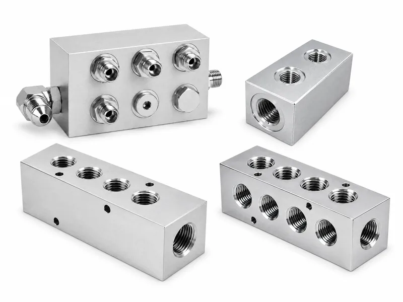
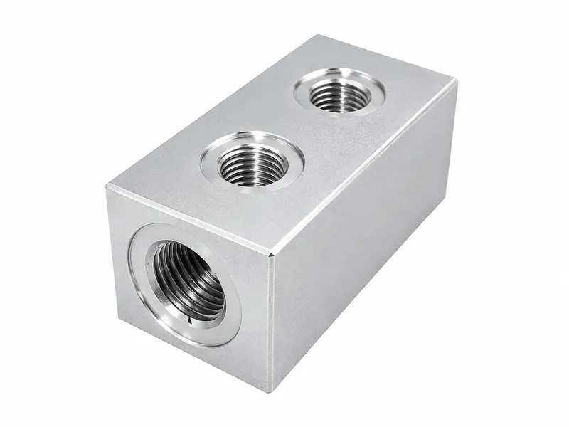
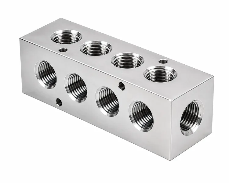
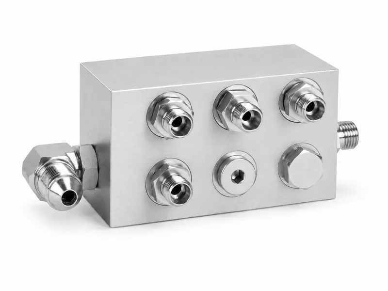
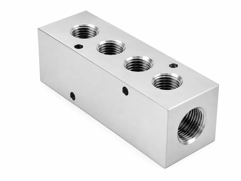
A hydraulic manifold block is a machined block that integrates internal passages, ports, valve cavities, mounting faces and plug locations. It routes and distributes fluid and provides interfaces for hydraulic components.
Hydraulic manifold blocks are machined blocks that integrate internal passages, ports, valve cavities, mounting faces and plug locations. The block routes and distributes fluid and provides interfaces for hydraulic components; the actual control function depends on the installed valves and circuit design. Integrated passages can reduce some external piping and connection points, but the block body itself should not be described as independently controlling hydraulic oil flow.
| Product Type | Machined hydraulic manifold blocks with internal passages, ports, valve cavities, mounting faces and plug locations |
|---|---|
| Materials | Carbon steel, stainless steel and aluminum alloy; other materials subject to drawing, pressure, media, corrosion, fatigue and application review |
| Manufacturing Process | CNC milling, drilling, tapping, boring or reaming, cartridge-cavity and mounting-face machining, cross-passage machining, deburring, cleaning, plug preparation and final inspection according to the drawing |
| Pressure Requirement | Confirm according to material and grade, minimum wall sections, passage and cavity geometry, port and plug design, sealing interfaces, mounted components, media, temperature, pressure cycle and validation requirements |
| Passage Closure / Plugs | Cross-drilled passages require drawing-specified closure plugs or sealing structures compatible with the passage, material, pressure, media and service requirements |
| Surface Treatment | Material-compatible finishes such as trivalent zinc plating, zinc-nickel coating, black oxide or phosphating for suitable steel blocks; anodizing or conversion coating for suitable aluminum blocks; passivation or natural finish for stainless steel, subject to drawing and order requirements |
| Tolerance Requirement | Port positions, cavity geometry, mounting faces, passage intersections, thread depths and other critical features are controlled according to the drawing, mating components, circuit function and agreed inspection plan |
| Drawing / Sample Support | 2D drawings, 3D models, mating-component data and physical samples are accepted |
| Component Type | Main Function / Connection Method / Manufacturing Method | Manufacturing Focus / Main Advantage | Typical Use |
|---|---|---|---|
| Hydraulic Manifold Blocks | Solid machined block with internal passages, valve cavities, ports, mounting faces and plug locations | Datum control, passage intersections, wall sections, cavity fit, sealing faces and cleanliness | Compact hydraulic circuits with installed valves and cartridges |
| Hydraulic Hose Assemblies | Flexible crimped hose connection | Bend radius, hose length and crimp quality | Moving or vibration areas |
| Threaded Adapter Connections | Connect separate pipe or hose ends | Thread form, sealing angle and torque | Serviceable hydraulic connections |
| Welded Tube Assemblies | Fixed rigid fluid-routing tube assembly | Tube route, weld identification and port orientation | Rigid OEM tube routing |
Manifold bodies are normally machined from block material with CNC-controlled ports, cavities and passages.
Cross-drilled passages reduce some external tubing and connection points without making a blanket leakage claim.
Valve cavities, mounting patterns, ports and sealing lands must match the mating valves, cartridges and fittings.
The body provides passages and interfaces; pressure, direction and flow control depend on installed valves and circuit design.
Intersecting passages, blind holes, threads, cavities and grooves require controlled deburring, cleaning and protection.
Used to integrate ports and installed valves in compact power-unit circuits.
Machined blocks for equipment circuits where the approved schematic defines the function.
Custom blocks for implement control circuits with specified valves and port standards.
Blocks for presses, lifting equipment and fixtures requiring compact hydraulic connections.
Made-to-drawing blocks matched to existing valves, plugs and mounting interfaces.
1. Provide the latest hydraulic schematic and drawing revision.
2. Confirm the circuit function and installed valve or cartridge list.
3. Confirm all valve cavities, mounting patterns, port standards and thread sizes.
4. Confirm internal passage diameters, intersections, drilling directions and closure locations.
5. Confirm material, grade, pressure cycle, media, temperature and corrosion requirements.
6. Confirm minimum wall sections and critical geometry through the approved design.
7. Confirm plug type, sealing method and installation requirements.
8. Confirm valve mounting faces, sealing lands, O-ring grooves and flatness requirements.
9. Confirm surface treatment and areas that must remain uncoated.
10. Confirm deburring, cleaning, flushing and cleanliness requirements.
11. Confirm dimensional, passage, leak, pressure, functional or fatigue testing requirements.
12. Provide 2D drawings, 3D models, mating-component data and samples when available.
Hydraulic manifold blocks require coordinated control of ports, valve cavities, mounting faces, cross-drilled passages and closure locations. The machining datums and passage intersections must be defined so the circuit matches the approved schematic without unintended connections or inadequate wall sections.
The manifold body provides passages and mounting interfaces. Directional, pressure and flow-control functions depend on the installed valves, cartridges, plugs and circuit arrangement. Without the corresponding valves and plugs, the block body does not automatically provide directional, pressure-regulating or flow-control functions.
Internal passage intersections, hole depths and drilling directions are machined from defined datums. Cross holes must not create weak wall sections, unintended connections or interference with valve cavities, flow paths or mounting faces.
Deburring and cleaning are critical at blind holes, intersecting passages, threaded ports, valve cavities and sealing grooves. Visible burr removal does not prove that every hidden intersection is acceptable. Internal cleanliness, flushing and particle inspection are performed only when specified by the drawing, order or validation plan, and ports, cavities and sealing faces should be protected after cleaning.
Dimensional inspection, plug inspection and passage verification do not by themselves establish a working-pressure rating. Leak, proof-pressure, functional or fatigue testing is arranged only when specified. Plug installation or testing is performed only when included in the drawing and order scope.
Grinding, honing, heat treatment or other secondary processes are applied only when specified. Any welded attachment is a separate project-specific feature and must be reviewed independently; it is not a standard substitute for machined internal passages.
Specific material grades are confirmed by drawing and order. Pressure cannot be determined by material name alone; effective wall sections between cross holes, valve cavities, passages and outside surfaces must be confirmed with the approved design and validation requirements.
Surface treatment is selected by material and function. Valve mounting faces, cavities, sealing grooves, threads and plug seats may require masking, and coating buildup can affect fit, so requirements should be defined by drawing and order.
Please share the latest hydraulic schematic, drawing revision, valve or cartridge list, material grade, port standards, passage details, plug requirements, finish, cleanliness notes and inspection requirements before quotation.
Application information such as media, temperature, pressure cycle, mounted components, corrosion exposure and packaging requirements helps us confirm machining risk and inspection focus.
We manufacture hydraulic manifold blocks according to customer drawings, schematics, samples or confirmed technical requirements, using CNC machining of solid block material, internal passages, ports, cavities and mounting interfaces.
Integrated passages can reduce some external piping and connector count, while the actual control function remains dependent on the installed valves, cartridges, plugs and circuit design.
Check block material against drawing and order requirements.
Review datums, drilling directions, cavity locations and closure positions before machining.
Machine ports, threads, mounting faces and valve cavities to drawing and mating-component data.
Control passage direction, depth and intersections from defined datums.
Inspect critical threads, cavity geometry, sealing lands and mounting interfaces.
Check passage relationships and effective wall sections according to the approved design.
Remove hazardous burrs at intersections, blind holes, threads and cavities.
Clean and protect ports, valve cavities and sealing faces according to requirements.
Confirm plug seats, sealing grooves and mounting faces before delivery or assembly.
Perform final inspection and any specified testing only according to the drawing, order or validation plan.
What is a hydraulic manifold block?
A hydraulic manifold block is a machined block that integrates internal passages, ports, valve cavities, mounting faces and plug locations. It routes and distributes fluid and provides interfaces for hydraulic components.
Does the manifold block itself control pressure or flow?
The block provides internal passages and mounting interfaces. Pressure, directional and flow-control functions depend on the installed valves, cartridges, plugs and circuit design.
How is a manifold block manufactured?
It is normally machined from solid material by CNC milling, drilling, tapping, boring or reaming, cartridge-cavity and mounting-face machining, cross-passage machining, deburring, cleaning and final inspection according to the drawing.
Is welding a standard manifold-block manufacturing process?
The manifold body is normally machined from solid material. Welding is not a standard substitute for CNC-machined internal passages; any welded attachment requires separate project review.
Which materials are available?
Carbon steel, stainless steel and aluminum alloy are typical options. Other materials are reviewed according to drawing, pressure, media, corrosion, fatigue and application requirements.
How is working pressure confirmed?
Working pressure is confirmed from material and grade, minimum wall sections, passage and cavity geometry, port and plug design, sealing interfaces, mounted components, media, temperature, pressure cycle and validation requirements.
How are cross-drilled passages closed?
Cross-drilled passages require drawing-specified closure plugs or sealing structures compatible with the passage, material, pressure, media and service requirements.
How are burrs and internal cleanliness controlled?
Intersecting passages, blind holes, threaded ports, valve cavities and sealing grooves require deburring and cleaning. Internal cleanliness, flushing and particle inspection are performed only when specified by the drawing, order or validation plan.
Are all manifold blocks pressure tested?
No blanket test claim is made. Leak, proof-pressure, functional or fatigue testing is arranged only when specified by the drawing, order or validation plan.
What surface treatments are available?
Material-compatible finishes may include trivalent zinc plating, zinc-nickel coating, black oxide or phosphating for suitable steel blocks, anodizing or conversion coating for suitable aluminum blocks, and passivation or natural finish for stainless steel.
How are tolerances confirmed?
Port positions, cavity geometry, mounting faces, passage intersections, thread depths and other critical features are controlled according to the drawing, mating components, circuit function and agreed inspection plan.
What information is required for quotation?
Provide the latest hydraulic schematic and drawing revision, valve or cartridge list, port standards, passage details, material, pressure cycle, media, finish, cleanliness, testing requirements, 2D drawings, 3D models and samples when available.
Tell us your requirements and available technical information so we can review the project and prepare a quotation.