Hydraulic Cylinder Components
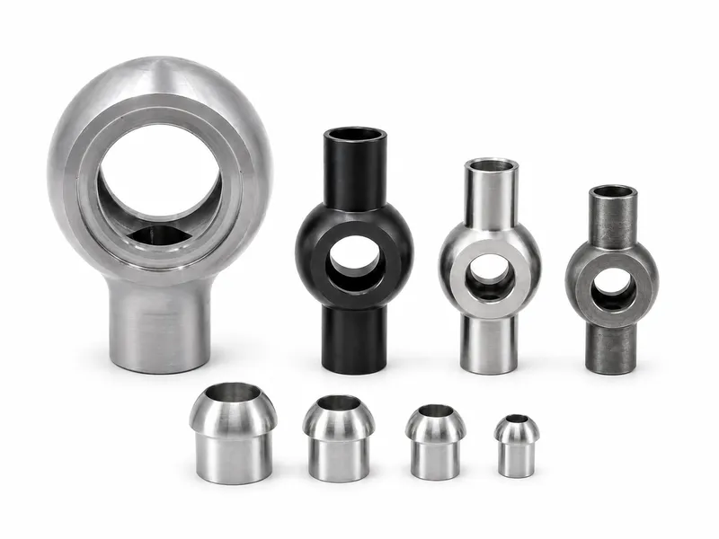
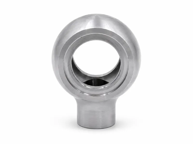
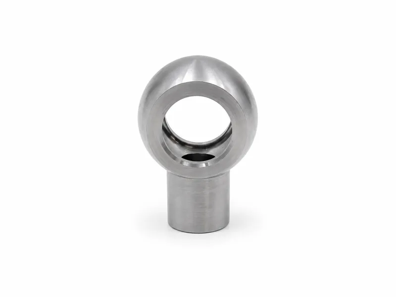
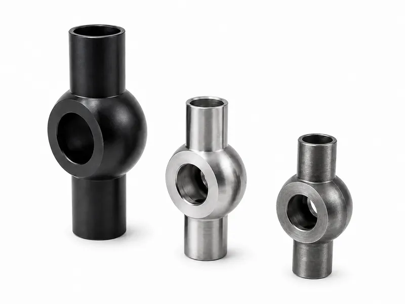
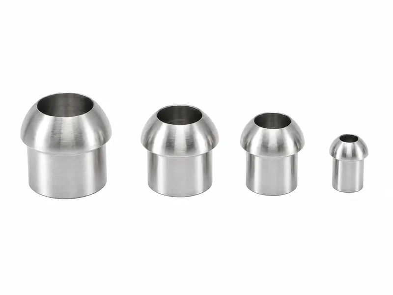
Hydraulic cylinder parts are drawing-specific components used for pressure separation, rod guidance, sealing support, load transfer, mounting or fluid connection according to their individual function. A piston, gland, end cap, rod end, clevis, bushing and welded port do not perform the same duty and must be specified separately.
Hydraulic cylinder parts include pistons, glands or rod glands, end caps or heads, rod ends, clevis ends, bushings, cylinder ports, weld-on ends or bosses and other drawing-specific components. Pistons normally support pressure-chamber separation and piston seals; glands guide the rod and locate rod seals, wipers and guide rings; end caps may close the cylinder and may form a pressure boundary depending on the design. Rod ends and clevises mainly transfer mechanical loads, bushings address pin fit, oscillation and wear, and ports or weld-on ends may be pressure-boundary features only when the structure and welding requirements are defined. The applicable pressure, sliding, guiding, sealing, welding or load-bearing requirements depend on the individual component and complete cylinder design.
| Product Type | Drawing-specific hydraulic cylinder parts, including pistons, glands, end caps, rod ends, clevises, bushings, cylinder ports and weld-on ends |
|---|---|
| Materials | Carbon steel, alloy steel and stainless steel according to component function and drawing requirements; other materials subject to strength, wear, corrosion, welding and application review |
| Manufacturing Process | CNC turning, milling, drilling, tapping, boring or reaming, seal-groove machining, pin-hole and thread machining, and drawing-specified grinding, polishing, heat treatment or welding where applicable to the individual component |
| Pressure Requirement | For pressure-retaining components, confirm according to material and grade, geometry, effective wall sections, seal arrangement, threads or retention method, mating parts, welding requirements, media, temperature, pressure cycle and complete cylinder validation |
| Mechanical Load Requirement | For rod ends, clevises, pin joints and mounting components, confirm according to material, geometry, pin diameter, bearing area, thread engagement, load direction, articulation, fatigue duty and complete cylinder or machine design |
| Surface Treatment | Component- and material-specific finishes such as trivalent zinc plating, zinc-nickel coating, black oxide or phosphating for suitable steel parts; passivation or natural finish for stainless steel; drawing-specified wear, sliding or corrosion treatments where applicable |
| Tolerance Requirement | Seal grooves, bores, outside diameters, pin holes, threads, shoulders, mounting faces and other critical features are controlled according to the drawing, seal system, mating parts, component function and agreed inspection plan |
| Drawing / Sample Support | 2D drawings, 3D models, mating-component data, seal information and physical samples are accepted for review |
| Component Type | Main Function | Design Focus | Typical Review Items |
|---|---|---|---|
| Piston | Pressure-chamber separation and piston seal support | Piston seal and wear-ring grooves, outside-diameter relationship with cylinder bore and connection to the piston rod according to drawing | Seal system, bore fit, rod connection and complete cylinder validation |
| Gland / Rod Gland | Rod guidance, seal installation and end closure according to design | Rod-seal, wiper and guide-ring locations plus fit with cylinder tube, head or retaining structure | Rod diameter, seal data, guide arrangement and retaining method |
| End Cap / Head | Cylinder closure, pressure-boundary or mounting function according to design | Ports, seal interfaces, tube connection and retention details | Pressure boundary, sealing, threads, welding or mounting interfaces |
| Rod End / Clevis | Mechanical load transfer to the linkage or machine | Thread, pin-hole, bearing area and linkage geometry; load and fatigue requirements are not determined only by hydraulic pressure | Load direction, articulation, pin fit, thread engagement and fatigue duty |
| Bushing | Pin guidance, oscillation or wear interface | Material, lubrication and fit according to mating pin and housing | Mating pin, housing bore, wear interface and lubrication condition |
| Cylinder Port / Welded End | Fluid connection or tube-end structure | Weld preparation, orientation and pressure-boundary requirements according to drawing | Base material, joint design, weld distortion and specified inspection |
Each piston, gland, end cap, rod end, clevis, bushing and port is reviewed for its own pressure, guiding, sealing, mounting or load-transfer duty.
Seal-groove geometry must match the specified seal system, mating diameter, pressure direction, clearance, media, temperature and cylinder design.
Rod ends, clevises and pin holes are reviewed by load direction, bearing area, thread engagement, articulation and fatigue duty.
Machined weld-on ports or ends require separate review of base material, joint design, orientation, welding process, post-weld distortion and specified inspection.
Component inspection confirms individual part features; complete-cylinder pressure, leakage, friction, load and durability performance requires assembly-level validation when required.
Hard chrome or another rod-surface treatment applies only to drawing-specified piston-rod or sliding surfaces and is not a default finish for all cylinder parts.
Drawing-specific parts for excavator, loader, crane and attachment cylinders.
Components for tractor, harvester and implement actuators.
Parts for lifting tables, hoists, forklifts and handling equipment cylinders.
Machined components for presses, fixtures and automated hydraulic actuators.
Custom parts for mobile machinery and vehicle-mounted cylinder assemblies.
Made-to-drawing parts for service, replacement and new actuator development.
1. Identify the exact component type and function.
2. Provide the latest cylinder assembly drawing and component drawing.
3. Confirm whether the component is pressure-retaining, sliding, guiding, load-bearing, welded or only a mounting feature.
4. Confirm mating tube, rod, pin, seal, thread and retaining structure.
5. Confirm material grade, heat-treatment condition and raw-material form.
6. Confirm seal-groove, wear-ring, guide-ring or wiper requirements where applicable.
7. Confirm pressure, mechanical load, fatigue, speed, stroke, media and temperature requirements relevant to the component.
8. Confirm threads, pin holes, bores, outside diameters, datums and critical tolerances.
9. Confirm welding requirements separately for weld-on ports or ends.
10. Confirm surface treatment, sliding-surface treatment and protected areas.
11. Confirm dimensional, material, weld, leak, pressure or assembly inspection requirements.
12. Provide drawings, mating-component data, seal information and samples for quotation.
Different hydraulic cylinder parts perform different duties. Pistons, glands and end caps use seal grooves confirmed from the specific seal system; rod ends, clevises and pin holes are confirmed from mechanical load, connection method and fatigue requirements; bushings are confirmed from fit, wear, lubrication and oscillation requirements.
Ports and weld-on ends require separate welding and pressure-boundary review. Machining inspection alone does not establish the pressure integrity of the completed welded cylinder assembly, and weld distortion may affect holes, faces, threads and sealing features.
Final pressure, leakage, friction, stick-slip, cushioning, load and service performance depend on the complete cylinder design and assembly, including tube, rod, seals, end closures, welds, threads, mounting parts and the lowest applicable component.
Material grade and condition are confirmed according to the component function, load, pressure boundary, wear interface, weldability, corrosion exposure and drawing requirements. Copper-alloy or engineering-plastic items are reviewed only for specific bushing, guiding or wear components; aluminum alloy is reviewed only for specific light-load, corrosion or special structures.
Seal grooves, seal-lip contact areas, threads, fitted bores, pin holes and welding areas may need coating control or masking according to the drawing. Roughness, roundness, cylindricity, concentricity, flatness and hardness are confirmed by the drawing rather than by one common tolerance for every part.
Please share the latest drawing revision, cylinder assembly drawing, mating-component data, seal information, material and heat-treatment notes, surface-treatment requirements, inspection requirements, target quantity and samples when available.
Also confirm whether the part is pressure-retaining, sliding, guiding, load-bearing, welded or only a mounting feature so machining and inspection scope can be reviewed correctly.
We manufacture hydraulic cylinder parts according to customer drawings, samples or confirmed technical requirements. Turning, boring, groove machining, hole machining, thread machining, welding preparation, grinding, polishing, heat treatment and finishing are arranged only where applicable to the individual component and drawing.
Material, hardness, nondestructive, leak, pressure, fatigue or assembly tests are arranged only when specified by the drawing, order or validation plan.
Confirm whether the part separates pressure, guides the rod, supports seals, transfers mechanical load, mounts the cylinder or connects fluid.
Inspect drawing-specified groove, bore, OD, guide-ring, wear-ring and wiper locations without assuming one groove standard for all parts.
Check rod-end threads, shoulders, clevis pin holes and bearing areas according to drawing and agreed inspection plan.
Review weld-on ports or ends separately for base material, joint design, orientation, post-weld distortion and specified inspection.
Single-part dimensional inspection is not a complete-cylinder pressure test, leak test or load and fatigue validation.
What hydraulic cylinder parts can be manufactured?
Pistons, glands or rod glands, end caps or heads, rod ends, clevis ends, bushings, cylinder ports, weld-on ends or bosses and other drawing-specific components can be manufactured according to the confirmed part drawing.
Do all cylinder parts retain hydraulic pressure?
No. Pistons, glands, end caps, rod ends, clevises, bushings and ports have different functions. Pressure-boundary, sliding, guiding and load-bearing requirements must be identified separately.
How are piston and gland seal grooves confirmed?
Seal-groove geometry must match the specified seal system, mating diameter, pressure direction, clearance, media, temperature and cylinder design. No single groove profile or surface requirement applies to every piston, gland or end cap.
How are rod-end and clevis loads confirmed?
Rod-end and clevis requirements are confirmed from material, geometry, pin diameter, bearing area, thread engagement, load direction, articulation, fatigue duty and the complete cylinder or machine design.
What materials are available?
Carbon steel, alloy steel and stainless steel are selected according to component function and drawing requirements. Other materials are reviewed for strength, wear, corrosion, welding and application requirements.
Is hard chrome applied to all cylinder parts?
No. Hard chrome or another rod-surface treatment applies only to drawing-specified piston-rod or sliding surfaces. Other cylinder parts use material- and function-specific finishes.
How is working pressure confirmed?
For pressure-retaining components, pressure suitability is reviewed with material, geometry, effective wall sections, seals, threads or retention, mating parts, welding requirements, media, temperature, pressure cycle and complete cylinder validation.
Are individual parts pressure tested?
Individual component inspection confirms the specified features of the part. Complete-cylinder pressure, leakage, friction, load and durability performance must be validated at the cylinder or machine assembly level when required.
How are weld-on ports or ends handled?
Machined weld-on ports or ends require separate review of base material, joint design, orientation, welding process, post-weld distortion and specified inspection.
How are tolerances and surface finish confirmed?
Seal grooves, bores, outside diameters, pin holes, threads, shoulders, mounting faces, roughness, geometry and hardness are controlled according to the drawing, seal system, mating parts, function and agreed inspection plan.
What information is required for quotation?
Please provide the latest assembly and component drawings, mating tube, rod, pin, seal, thread and retaining data, material and heat-treatment condition, welding and surface-treatment requirements, inspection requirements, quantity and samples when available.
Can parts be manufactured from samples?
Samples can help identify geometry and manufacturing risk, but drawings, mating-component data and seal information are recommended for repeatable production and quotation.
Tell us your requirements and available technical information so we can review the project and prepare a quotation.