Drawing-specific rigid tube assemblies combining straight or bent tubing, CNC-machined weld fittings, bosses, flanges and mounting brackets for hydraulic and industrial fluid routing.
Wei Xing Machinery manufactures custom welded tube assemblies and welded tubing assemblies for fixed hydraulic and industrial fluid routes. Each assembly is produced from customer drawings, 3D models or approved samples using tube cutting, bending or forming, machined fittings, fixture assembly, drawing-specified welding, post-weld cleaning and final inspection.
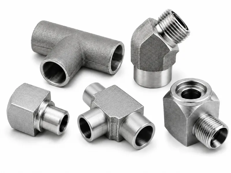
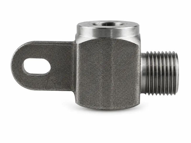
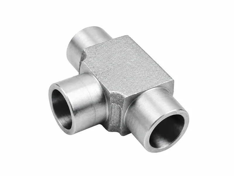
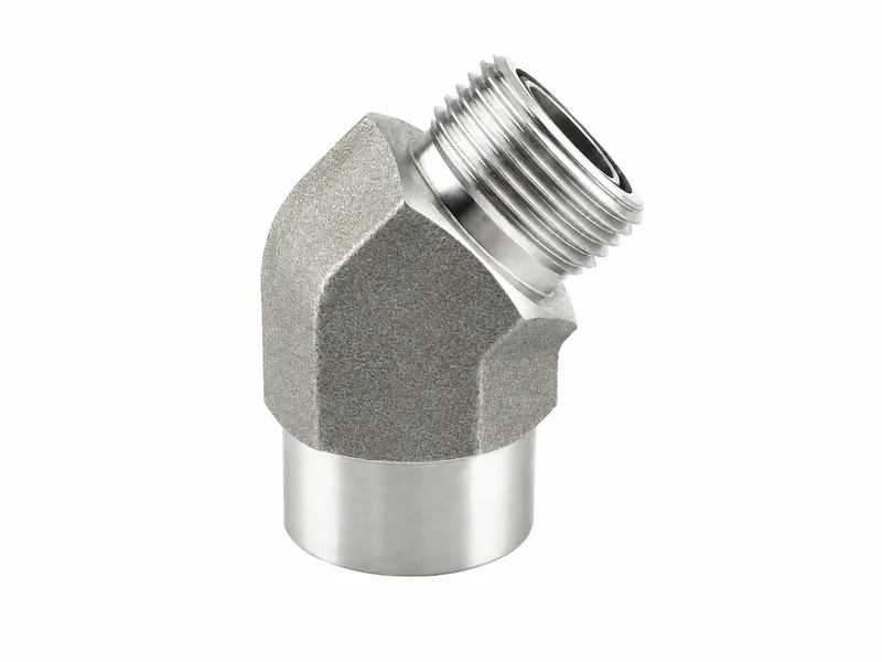
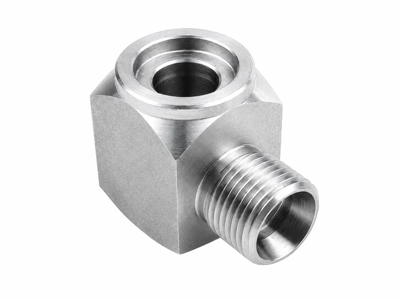
A welded tube assembly combines rigid tubing with machined fittings, bosses, branches, flanges or mounting brackets to create a repeatable fluid route for hydraulic and industrial equipment. We review tube centerlines, bend radii, end orientation, weld locations, mounting points and sealing interfaces before quotation.
Connection ends may include drawing-specified JIC, ORFS, BSP, NPT, flange or custom interfaces. Pressure-boundary tube joints, structural support welds and connection-end sealing functions must be identified separately in the drawing and manufacturing requirements.
| Product Type | Drawing-specific rigid welded tube assemblies for fixed hydraulic and industrial fluid routing. |
|---|---|
| Typical Components | Straight or bent tubing, CNC-machined weld fittings, bosses, branches, flanges, mounting brackets and drawing-specified connection ends. |
| Materials | Carbon steel and stainless steel. Other weldable materials are reviewed according to the drawing, joint design, media, corrosion exposure and manufacturing requirements. |
| Tube Geometry | Tube outside diameter, wall thickness, centerline route, bend radii, end-to-end dimensions and orientation are controlled according to the approved drawing. |
| Connection Ends | Drawing-specified JIC, ORFS, BSP, NPT, flange, weld-end or custom-machined interfaces. |
| Manufacturing Process | Tube cutting, bending or forming, CNC machining of fittings, weld-end preparation, fixture assembly, drawing-specified welding, post-weld cleaning and final inspection. |
| Surface Finish | Material-compatible finishes such as trivalent zinc plating or zinc-nickel coating for suitable carbon-steel components, and passivation or natural finish for stainless steel, subject to drawing requirements. |
| Inspection Basis | Assembly datums, tube route, end orientation, mounting points, weld requirements, sealing interfaces and drawing-specified inspection or testing requirements. |
| Drawing Support | 2D drawings, 3D models, physical samples and assembly information can support quotation and manufacturing review. |
| Component Type | Construction | Main Design Focus | Typical Application |
|---|---|---|---|
| Welded Tube Assemblies | Rigid tube route with drawing-specified welded joints, machined fittings and optional mounting brackets. | Tube centerline, weld locations, port orientation, mounting points, cleanliness and inspection scope. | Fixed hydraulic or industrial fluid routes in OEM equipment. |
| Hydraulic Hose Assemblies | Flexible hose with crimped or reusable end fittings. | Hose length, bend radius, movement, vibration and crimp compatibility. | Moving joints, vibration areas and service-replaceable connections. |
| Custom Bent Tubes | Formed rigid tubing with fewer welded joints. | Bending radius, springback, end forming and installation route. | Compact fixed tube routes where the geometry can be formed from one tube. |
| Threaded Adapter Connections | Separate components joined by threaded or face-seal interfaces. | Thread form, sealing structure, assembly access and serviceability. | Detachable hydraulic connections and equipment interfaces. |
Tube centerlines, bend radii and end-to-end dimensions must match the approved assembly route.
Port direction, sealing faces, thread orientation and wrench access must match mating equipment.
Drawings should distinguish joints that retain fluid pressure from bracket or support welds.
Joint geometry, gap, alignment and component fit-up are reviewed before drawing-specified welding.
Bracket position, mounting-hole location and equipment clearance are controlled from assembly datums.
Fixtures, welding sequence and intermediate inspection help control route, angle, flatness and end orientation.
Post-weld cleaning and end protection requirements are reviewed according to the drawing and order scope.
Threads, sealing faces, internal surfaces and fitted areas are protected or masked when required.
The manufacturing route is selected according to tube geometry, material, joint design, connection ends and the approved drawing. Not every assembly requires every operation listed below.
Confirm the latest drawing revision, material grade, tube size, wall thickness and assembly requirements before production.
Cut tubing to the required length and prepare ends for bending, welding or connection interfaces.
Form drawing-specific routes while reviewing bend radii, centerlines, straight sections and end orientation.
Machine weld fittings, branches, bosses, flanges and connection features according to the approved design.
Review joint preparation, alignment, gap and component fit-up before welding.
Use assembly fixtures and intermediate checks to control routing, port direction, brackets and mounting points.
Perform welding according to the approved material, joint design and project manufacturing requirements.
Check critical route dimensions and orientation before later operations make correction difficult.
Remove chips, spatter, loose oxides and residual contamination according to the required cleaning scope.
Review coating compatibility, masking and protected functional surfaces according to material and drawing requirements.
Verify assembly datums, end orientation, threads, sealing interfaces, mounting points and key dimensions.
Leak, pressure, nondestructive or other testing and special end protection are included only when agreed during quotation.
Material grade, tube form, fitting material, weld-end design and surface finish are reviewed according to the drawing, media, temperature, corrosion exposure and manufacturing requirements.
Typical material options include carbon steel and stainless steel. Other weldable materials are reviewed only when the material combination, joint design and project requirements are clearly defined.
Suitable carbon-steel components may use trivalent zinc plating, zinc-nickel coating or another drawing-specified finish. Stainless-steel components may use passivation or a natural finish. Threads, sealing faces, tube interiors and fitted areas are protected or masked when required.
Review drawing revision, material, tube size, wall thickness and connection requirements.
Check centerlines, bend locations, straight sections and end distances before assembly.
Review joint preparation, alignment and component fit-up before welding.
Control tube route, bracket location, port direction and mounting interfaces during assembly.
Inspect accessible weld appearance according to the agreed manufacturing and acceptance requirements.
Verify assembly datums, end orientation, mounting points, threads and sealing interfaces.
Remove manufacturing contamination according to the specified scope and protect clean ends and functional surfaces.
Testing is performed only when the required method, pressure, duration and acceptance criteria are included in the approved order scope.
Fixed hydraulic tube routes for excavators, loaders, cranes, attachments and related equipment.
Rigid tubing assemblies for tractors, harvesters and hydraulic implements.
Compact tube routes connecting pumps, valves, filters, reservoirs and auxiliary components.
Fluid lines for presses, lifting equipment, fixtures and production systems.
Rigid hydraulic routing for lifting, conveying and mobile handling equipment.
Made-to-drawing assemblies where tube route, end orientation and mounting features must be reproduced.
Latest 2D drawings, 3D models, assembly drawings, revision information and physical samples when available.
Tube material, grade, outside diameter, wall thickness and fitting or boss materials.
Tube centerlines, bend radii, end-to-end dimensions, mounting datums, bracket positions and installation space.
Pressure-boundary weld locations, support welds, joint details, JIC, ORFS, BSP, NPT, flange or custom end interfaces.
Media, temperature, system pressure, operating duty, vibration, corrosion exposure and mating equipment.
Prototype or production quantity, surface finish, cleanliness, leak or pressure testing, documentation, packaging and end protection.
The final pressure capability and system suitability of a welded tube assembly depend on the tube material and dimensions, joint design, welded connections, machined fittings, end interfaces, media, temperature and operating duty. Visual and dimensional inspection alone does not establish pressure integrity.
Leak, proof-pressure, burst, impulse, nondestructive or other testing is performed only when the required method, pressure, duration, sample quantity and acceptance criteria are included in the approved drawing, order or validation plan.
What is a welded tube assembly?
A welded tube assembly is a drawing-specific rigid fluid-routing component made from straight or bent tubing, machined fittings, bosses, branches, flanges or mounting brackets.
How is it different from a hydraulic hose assembly?
A welded tube assembly provides a fixed rigid route, while a hose assembly provides flexibility for movement, vibration or service replacement.
What materials are available?
Carbon steel and stainless steel are typical options. Other weldable materials are reviewed according to the drawing, joint design and project requirements.
Which connection ends can be included?
Assemblies may include drawing-specified JIC, ORFS, BSP, NPT, flange, weld-end or custom-machined interfaces.
How are tube routing and port orientation controlled?
Assembly fixtures, datum checks and intermediate dimensional inspection help control tube centerlines, end direction, bracket positions and mounting points.
Are all welds pressure-boundary welds?
No. Drawings should distinguish welded joints that retain fluid pressure from brackets or support welds that provide mechanical positioning.
Are all welded tube assemblies pressure tested?
No blanket test claim is made. Leak, pressure or additional testing is performed only when the method and acceptance criteria are included in the approved order scope.
What information is required for quotation?
Provide drawings or models, tube and material specifications, route dimensions, connection ends, weld requirements, operating conditions, quantity, finish and inspection requirements.
Share your tube size, route, connection ends, material, quantity and inspection requirements so we can review the assembly and prepare a quotation.